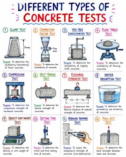
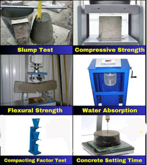
#Grade of Concrete, #Grade of Steel, #Compression Strength Test, Block, Slump & #Earth Quake.
Grade of Concrete:
In international practice, construction drawings typically specify the concrete grade rather than the mixing ratio. The final mixing ratio is determined through a trial-based mix design process to ensure the concrete achieves its required ultimate strength. Let us explore the various grades of concrete.
Ordinary Concrete:
√ M 5 OR 5 N/mm 2 OR 725 PSI, Ratio 1:5:10
√ M 7.5 OR 7.5 N/mm 2 OR 1087.5 PSI, Ratio 1:4:8
√ M 10 OR 10 N/mm 2 OR 1450 PSI, Ratio 1:3:6
√ M 15 OR 15 N/mm 2 OR 2175 PSI, Ratio 1:2:4
√ M 20 OR 20 N/mm 2 OR 2900 PSI, Ratio 1:1.5:3
Standard Concrete:
√ M 25 OR 25 N/mm 2 OR 3525 PSI, Ratio 1:1:2
√ M 30 OR 30 N/mm 2 OR 4350 PSI, Mix Design [1:0.75:1.5]
√ M 35 OR 35 N/mm 2 OR 5075 PSI, Mix Design [1:0.5:1]
√ M 40 OR 40 N/mm 2 OR 5800 PSI, Mix Design [1:0.25:0.5]
Note: [1M equals 145 PSI; a mix design is mandatory for grades ranging from M25 to M70.]
The quantity of coarse aggregate (stone chips) should be 1.5 to 2 times the amount of fine aggregate (sand) used in the concrete. The coarse aggregate component should consist of 70% '20 mm down-graded' material and 30% '12 mm down-graded' material.
For standard graded concrete, 350–400 kg of cement is used per cubic meter (cum) of concrete, along with an admixture. The water-cement ratio should be between 0.42 and 0.45, and it must never exceed 0.5.
Gradation of Rebar:
In viva-voce examinations, a common question is: "What is meant by a 500W TMT bar?" Let’s explore what this actually signifies.
The "500" (or 500 MPa) refers to the yield strength of the steel; in other words, this type of steel can safely withstand a stress of 72,500 PSI within its elastic limit.
The "W" stands for "weldable"—indicating that the steel can be joined through welding. There are many metals, such as cast iron, that cannot be joined or welded in this manner.
TMT stands for "Thermo-Mechanically Treated." In short, a TMT bar is a high-strength reinforcement produced through a thermo-mechanical process.
Note: Keep in mind that 1W is equivalent to 1 MPa or 145 psi. Therefore, 500W = 500 × 145 psi = 72,500 psi = 72.5 ksi (or "Grade 72").
Similarly, 400W = 400 × 145 psi = 58,000 psi = 58 ksi (or "Grade 60"), and 275W corresponds to "Grade 40" rebar.
Compressive Strength Test:
The compressive strength of concrete is generally tested in two ways:
-
Cylinder Test (specimen sizes: 4”x8” or 6”x12”)
-
Cube Test (specimen size: 6”x6”x6”)
Keep in mind that concrete testing is typically conducted at 3, 7, 14, 21, and 28 days. Let’s look at the percentage of strength that concrete attains over time:
Age vs. Strength Percentage
1 day: 16%
3 days: 40%
7 days: 65%
14 days: 90%
28 days: 99%
Note: Various studies have shown that the Cube Test yields results 15% to 20% higher than the Cylinder Test; therefore, for safety reasons, the Cylinder Test is preferable to the Cube Test.
Blocks made of Cement-Sand Mortar:
Blocks are essential for maintaining the clear cover of RCC members. It is important to ensure that the strength of these blocks is equal to the design strength of the concrete. Guidelines for the blocks are as follows:
-
The mix ratio for the blocks shall be 1:1 (Cement: Sand), and 100% Sylhet sand must be used.
-
The blocks must be cured for at least 7 days.
Note: To ensure that the blocks remain correctly positioned during the concreting process, it is advisable—where possible—to insert a piece of #24 SWG G.I. wire into each block; this allows the blocks to be securely tied to the steel reinforcement (rebars).
Alternatively, high-quality, ready-made blocks are now available in the market, which can easily help avoid these issues.
Slump Test of Concrete:
A slump test is performed to assess the workability of freshly mixed concrete. An excessive amount of water in the concrete mix can lead to segregation, while an insufficient amount may result in the formation of voids—both of which are detrimental to the quality of the concrete.
Slump is primarily of three types:
(i) True Slump
(ii) Shear Slump
(iii) Collapse Slump
In addition to these, there is another type known as Zero Slump.
Range of Slump:
(i) Very Low Slump [0–25 mm]: This is typically a "dry mix" type, used for road concrete where mechanical vibration is employed.
(ii) Low Slump [25–50 mm]: This is used for mass concrete, foundations with light reinforcement, bridge decks, or the upper structures of caissons, where handheld vibrators are used for compaction.
(iii) Medium Slump [50–100 mm]: Concrete prepared for RCC beams, slabs, and walls generally has a slump in the range of 50–100 mm. It is compacted either manually or by using a vibrating machine.
iv) High Slump [100–150 mm]: Typically, the concrete slump for RCC columns and retaining walls exceeds 100 mm. In structures such as piles or piers where the use of a vibrator is not feasible the concrete slump value is often 140–150 mm or even higher.
Note: Since a high slump is achieved by increasing the water content, an admixture must be used to maintain the concrete's workability, density and consistency.
Finally, let us examine the intensity and impact of earthquakes, specifically the relationship between Richter scale magnitude and intensity.
1. Richter scale magnitude 0–1.9 – Instrumental.
2. Richter scale magnitude 2–2.9 – Very minor.
3. Richter scale magnitude 3–3.9 – Minor.
4. Richter scale magnitude 4–4.9 – Light.
5. Richter scale magnitude 5–5.9 – Moderate.
6. Richter scale magnitude 6–6.9 – Strong.
7. Richter scale magnitude 7–7.9 – Destructive.
8. Richter scale magnitude 8 or higher – Catastrophic.
Clear Cover:
Clear cover refers to the distance from the outer face of the steel reinforcement to the outer face of the concrete. As we know, a clear cover is necessary to protect the steel from the harmful effects of the environment.
Furthermore, if an adequate clear cover is not provided, the reinforcement (steel) may fail—either due to corrosion caused by chemical reactions with oxygen or harmful salts (such as sodium) present in the air, or due to the expansion of the steel resulting from direct exposure to fire or high temperatures.
Let us now look at the typical clear cover values that are generally maintained:
√ Pile & Pile Cap: 3” OR 75 mm at all side.
√ Footing: 3” at all side.
√ Mat/ Raft: Bottom & Side 3”, Top 2” OR 50 mm.
√ Short Column/ Pedestal: 3” at all side.
√ Grade Beam: 2.5” to 3” at all sides.
√ Under Ground Water Tank: Outer Side 2.5” to 3” & Inner Side 2”
√ Typical Beam: 1.5”
√ Typical Slab & Stair: Bottom 1” Top ¾” & Side 1.5”
√ Column: 1.5” at all face
√ Over Head Tank: Water Face 2” & Outer Face 1” o 1.5"
√ Lift Core & Shear wall: 1.5” at all face.
Note: For elements in direct contact with the ground, a minimum concrete cover of 2.5” must be provided. According to the code, a minimum cover of 3/4" (20 mm) is mandatory; a tolerance of +/- 10 mm is acceptable.
Timing for Shutter Removal:
It must be remembered that shutters should only be removed once the concrete has attained sufficient strength to support its own dead load (self-weight). In a previous post, we discussed the rate at which concrete gains strength over time though this depends on factors such as the concrete grade, temperature, curing procedures, and formwork design. Under no circumstances should shutters be removed before 72 hours.
What do the codes say regarding the removal of formwork (shuttering)?
-
Columns or Vertical Walls: 48 to 72 hours; however, do not attempt to remove formwork from columns before 24 hours under any circumstances.
-
Beam or Slab Sides (outer faces of perimeter beams): 24 to 48 hours; ensure that the removal of side formwork does not cause the bottom formwork to loosen or become displaced.
-
Bottoms of Beams, Slabs, and Stairs: 21 to 28 days.
Precautions:
-
Shuttering should be removed starting from the mid-span (the center of the slab) and proceeding outward uniformly toward the beams or supports; the formwork for the beams themselves should be removed last.
-
In the case of cantilever slabs, removal should proceed from the free end toward the support.
-
Horizontal supports should be installed in two or three layers, connecting to the perimeter columns of the building, to ensure that no part of the removed shuttering falls to the ground.
Note: In case of an emergency, for spans shorter than 4.5 meters (14 feet), formwork removal may be permitted after 14 days. I am currently working on a project where the specifications suggest a minimum of 1 day for formwork removal for every foot of span length, with the condition that this duration cannot be less than 10 days.