
Topics: Shear Key, Casting Height, Lapping, Beam Column Joint, Construction Joint.
- Shear Key in Columns: In the context of columns, a 'shear key' is a mechanical groove, notch or a protruding structural element (such as a piece of steel embedded in concrete or a recess formed within the concrete) used to interlock two connected components and resist horizontal (shear) forces.
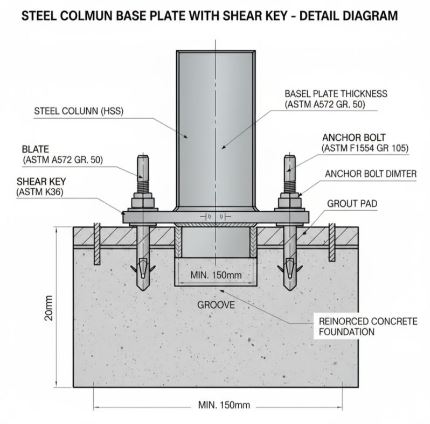
Designers typically recommend incorporating a shear key at construction joints (especially in columns) for two main reasons:
1. To increase the shear resistance capacity of the column.
2. To reduce the risk of displacement between adjacent segments of the column. Shear keys are generally 2 to 4 inches deep; it is essential to ensure that the recess is thoroughly cleaned before the subsequent concrete pour.
Tip: It is best to cover the recess with a piece of polyethylene the day after the initial pour, as this allows for easy removal later.
-
Column Casting Height: When pouring concrete into columns, the maximum free-fall height should be between 1.0 and 1.5 meters (5 feet) to prevent the heavier components from separating from the cement paste a phenomenon known as segregation.
In typical residential or commercial buildings, columns on each floor are generally cast to a height of 3.0 meters (approximately 9.6 to 10 feet). However, it is very rare for concrete to be poured to the full height at once without any form of control from above. which is called Total Single-Pour Height.
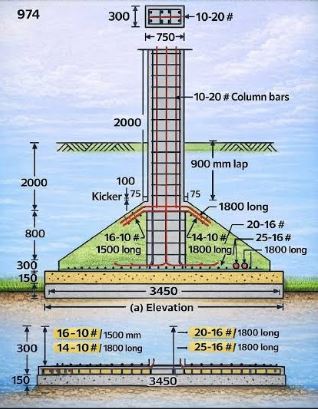
In many instances, contractors opt to cast columns to their full height in a single pour to expedite the work; however, this is highly inadvisable. Columns must be cast in two or more stages (lifts). Failure to do so can lead to the following issues:
1. Voids or honeycombing resulting from segregation, laitance, or bleeding can render the column fragile and structurally weak.
2. There is a risk of vertical displacement (shifting) or the failure of the shuttering (formwork).
3. Variations in the clear cover can lead to various issues, including the formation of cracks.
Recommendation: As a site engineer, you should never permit the casting of columns or walls to a height exceeding 1.5 meters (5 feet) in a single vertical lift.
-
Lapping & Spacers: Lapping and spacers are two distinct mechanical and manufacturing concepts, though both play an essential role in precision engineering, assembly alignment, and surface control.
-
Lapping: Lapping is a precision surface-finishing and material-removal process. It involves rubbing two surfaces a workpiece and a lapping tool or plate together with the aid of fine abrasive particles (which are either suspended in a wet slurry or embedded within the plate).
-
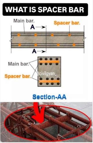
Spacers: A spacer is a mechanical component (often a simple, unthreaded tube, ring or flat piece) that is placed between two parts to maintain a specific, predetermined distance or gap between them.
Points to consider regarding lapping:
1. Generally, the lap length ranges from 24D to 44D in the compression zone and from 30D to 60D in the tension zone. Note: These figures account for both cases—with and without hooks. Furthermore, different consultants may follow different codes; however, according to many Indian consultants, a lap length of 50D can be adopted for both zones.
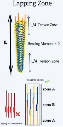
2. Care must be taken to ensure that no more than 50% of the reinforcing bars are lapped at any single location within a column or beam.
3. Lapping zone for columns: Laps should be provided within the L/2 or middle portion; the L/4 zones should be avoided, as maximum stress occurs there.
4. Lapping for top bars of beams: This should be located within the middle third of the span, as there is no negative moment in this zone.
5. Lapping for bottom bars of beams: This should be located within one-third of the span (L/3), as there is no positive moment in this zone.
6. The diameter of the spacer bars shall be 25 mm for beams and 12 mm for slabs, with a maximum spacing of 30” center-to-center (c/c). For beams, it must be ensured that the gap between the main bars and the extra bars does not exceed 1”.
-
Beam-Column Joint: A beam-column joint is a critical junction in a moment-resisting frame structure where horizontal beams connect to vertical columns. It serves as a primary load-transfer hub, channeling bending moments, shear forces and axial loads from the superstructure toward the foundation.
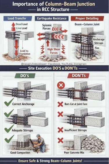
Depending on how many beams meet the column and their relative positions, joints are classified into three main types:
-
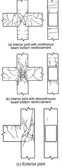
Interior Joint: A location in a floor plan where four beams connect to the four vertical faces of a column.
-
Exterior Joint: This is a location along the perimeter of a building where three beams one running straight through and two arriving from perpendicular directions connect to a column to form a structural assembly.
-
Corner Joint: This is located at the outer edge or corner of a building, where two beams connect to the mutually adjacent, perpendicular planes of a column.
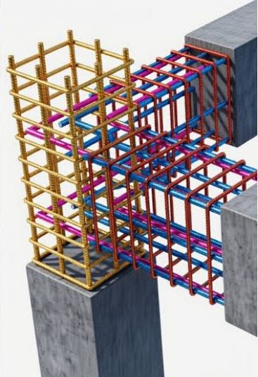
Most consultants suggest routing the beam reinforcement through the vertical reinforcement of the column. In practice, however, this is often not feasible because the clear cover for both the beam and the column is the same; consequently, in most cases, the reinforcement on one side of the beam is placed outside the column, while the reinforcement on the other side is placed inside.
Essential requirements for a beam-column joint:
1. At least two stirrups must be provided within the column at the joint location.
2. The first stirrup of the beam should be positioned at a distance equal to half the spacing from the column face, or at a distance of 2 inches from it.
3. The casting for this section must strictly adhere to the design strength specified for the column concrete; the concrete grade used for the column must be maintained. For other areas, the concrete grade specified for the slab must be used; otherwise, these sections will be structurally weak.
N.B.: Some suggest adjusting the spacing of stirrups near the column strip placing them closer together and widening the gaps elsewhere to facilitate the passage of beam reinforcement through the column. This practice is not consistent with proper design standards, as it is essential for the reinforcement bars in the beams, columns and slabs to remain straight to ensure effective load transfer.
-
Construction Joint: A construction joint is a planned interface or division within a concrete structure where newly poured concrete comes into contact with concrete that has already hardened (from a previous pour). Such joints are created when a phase of construction is completed, the daily limit for concrete pouring is reached, or when it becomes necessary to divide a large project into manageable segments.
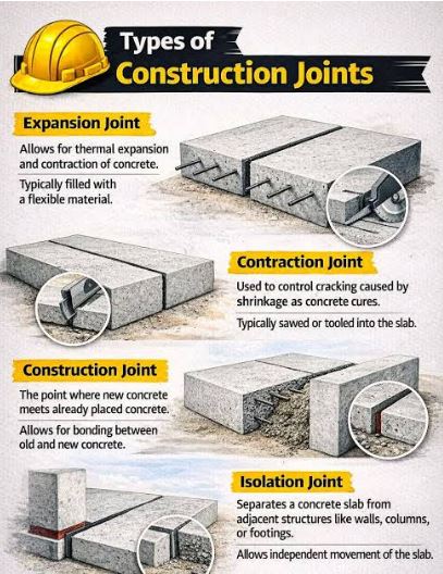
For various reasons, it becomes necessary to include construction joints in slabs or beams. Often, the casting of a slab is concluded along the edge of a beam or the casting of a beam is stopped right against the face of a column leaving exposed reinforcement bars which is entirely improper.
Important considerations for placing construction joints:
1. A construction joint must be located within the middle third of the span (i.e. at a distance of 2L/3 from the support), as shear stress is lower in this zone. It should never be placed within the L/3 distance from the support.
2. Construction joints in beams or slabs should be kept straight (vertical) rather than sloped; it is also advisable to provide a groove to serve as a shear key.
3. Proper clear cover for reinforcement bars and adequate lap lengths must be ensured.
4. Since this area is highly susceptible to water leakage, extreme care must be taken regarding the use of concrete vibrators and waterproofing admixtures.
- Hooks & Stirrups: Hooks are indispensable in the construction of earthquake-resistant buildings. When fabricating stirrups (or tie rings) and creating L-bends (hooks) in beam reinforcement, it is essential to ensure the required 'development length.'
Key requirements:
1. Stirrups for beams or columns must incorporate hooks bent at an angle of 135 degrees. The length of these hooks should be between 3D and 6D (where 'D' represents the diameter of the rebar), with a minimum length of 2 inches.
2. The length of a 90-degree L-bend (hook) in beam reinforcement must be 12D (where 'D' represents the diameter of the rebar).
- Groove Cutting in Columns: Grooves cut into columns often referred to as ‘architectural grooving’ or ‘V-grooving/recessed lines’ serve both aesthetic and functional purposes in building construction.

In many instances, grooves are cut into one or both sides of a column to accommodate door frames. This practice is highly detrimental to the column, which functions as a compression member.
Recommendation: There are two alternative methods for installing door frames:
1. You can install the frame by constructing a full-brick masonry wall (a 'kobla' or brick pier) adjacent to the column.
2. You can secure the frame to the column using clamps and drilled holes. However, I strongly recommend the first method; relying on clamps often leads to the plaster cracking and the clamps becoming exposed over time due to the tension exerted by the door frame.
Important guidelines for site engineers:
1. Lapping is not permitted for reinforcing bars with a diameter greater than 36 mm.
2. The spacing between 'chairs' (in both directions) must not exceed one meter.
3. The minimum diameter for dowel bars is 12 mm.
4. The diameter of the bars used for 'chairs' must not be less than 12 mm.
5. The area of longitudinal reinforcement must be at least 0.8% and at most 6% of the cross-sectional area.
6. Rectangular columns must contain at least 4 reinforcing bars, while circular columns must contain at least 6.
7. The main reinforcement bars for a slab must not be less than 8 mm in diameter; however, plain bars must not be less than 10 mm. Distribution bars must not be less than 8 mm. The diameter of the reinforcement bars must not exceed one-eighth of the slab's thickness. For example, if the slab thickness is 160 mm, the bar size cannot exceed 20 mm.
8. It is advisable that the slab thickness be no less than 125 mm.
9. The tolerance for the size of a concrete cube is +2 mm; that is, the dimension in any direction must not exceed the standard size by more than 2 mm.
10. Concrete should not be poured from a height greater than 1.5 meters.
11. The water absorption capacity of bricks must not exceed 15%.
12. The pH value must not be below 6.
13. The compressive strength of bricks must not be less than 3.5 N/mm².
14. 8 kg of binding wire is required per metric ton of steel rods.
15. During concrete casting, at least one set of samples must be collected for cylinder testing for every 100 cubic meters.