
Question: What is a generator?
Answer: A device that converts mechanical energy into electrical energy is called a generator. This conversion process requires the creation of a magnetic field.
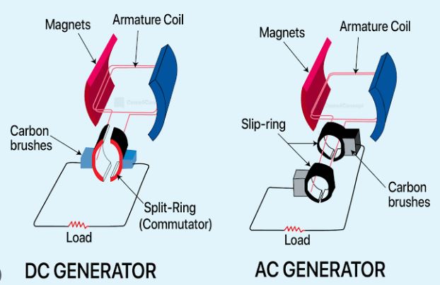
In a generator, coils of wire are placed on the armature. A prime mover (such as an engine) is required to rotate the armature within the magnetic field. When the armature coil is rotated inside the magnetic field, a voltage is generated in the armature conductors; this is known as EMF (Electromotive Force).
Generally Generators are two types:
1. AC generator
2. DC generator
Basic Principles of an Alternator (AC Generator):
Alternators are built based on the principle of electromagnetic induction. Like DC generators, alternators also consist of an armature and a magnetic field. In an alternator, the armature winding is mounted on a stationary structure known as the stator, while the magnetic coils are mounted on a rotating structure called the rotor. The armature and the core of the stator are secured to a cast-iron frame. Slots are cut into the inner part of the core to accommodate the windings. South and North poles are formed alternately around the outer periphery of the rotor. A DC supply—typically at 125 or 250 volts is passed through coils wound around these poles. In most cases, a small shunt generator, known as an 'exciter' and coupled to the rotor shaft is used to provide this DC current. The current from the exciter is delivered to the coils via brushes and slip rings.
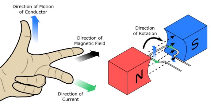
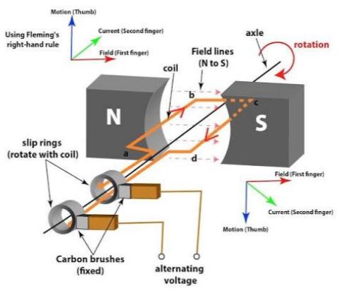
As the rotor begins to rotate, the magnetic field lines also rotate along with it. When these rotating magnetic field lines intersect the conductors placed in the slots of the stator, an electromotive force (EMF) is induced in each conductor, in accordance with the principles of electromagnetic induction. The direction of the induced EMF can be determined using Fleming's right-hand rule. Applying this rule, it is observed that when the south pole is positioned in front of a conductor, the direction of the induced electromotive force (EMF) and the resulting electric current is opposite to what occurs when the north pole is in that position. Consequently, the direction of the induced EMF and the electric current within the armature also changes.
Structure of an AC generator:
In the present day, AC generators are the most widely used. An AC generator consists of a field magnet, with a rectangular coil of wire wound around a soft iron core placed between the poles of the magnet. This soft iron core is known as the armature. The armature is rotated at a constant speed using mechanical energy—positioned precisely between the two poles of the magnet.
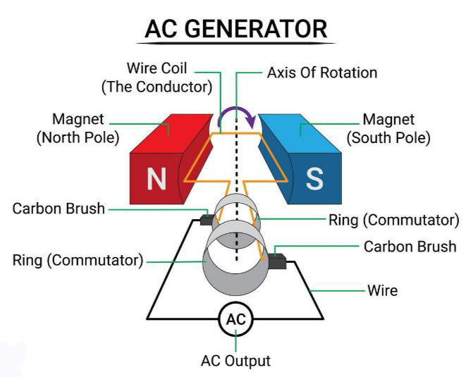
A rectangular coil is connected to two springs at its ends. These two springs can rotate along the same axis as the armature. Two carbon brushes are positioned such that they make contact with the springs as the armature rotates, and the resistance of an external circuit is connected to these brushes. Essentially, this describes the structural design of a generator.
Working principle of an AC generator:
When the armature is rotated, its coils cut across the magnetic field lines; in accordance with the principles of electromagnetic induction, an electromotive force (EMF) is induced within the coils. Since the two ends of the coils are connected to an external circuit, an alternating electric current is generated in the circuit. The magnitude of this induced electric current generally depends on the strength of the magnetic field and the rotational speed. During a single rotation of the coil, the direction of the induced electric current changes once; this is how electrical energy is generated from mechanical energy.
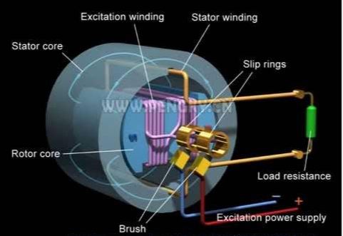
List of the various components of an alternator (AC generator):
An alternator consists of three main parts:
-
Stator
-
Rotor
-
Exciter
Stator: In large alternators, the stator consists of two types of components:
-
Frame or Yoke
-
Stampings
Rotor: There are two types of alternator rotors:
-
Salient pole
-
Non-salient pole
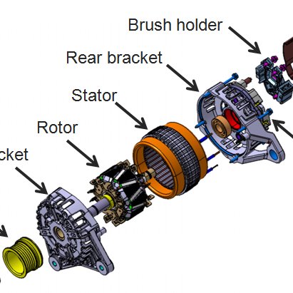
Types of AC Generators
There are two types of AC generators:
-
Asynchronous/Induction Generator
-
Synchronous Generator
1. Asynchronous/Induction Generator: An induction generator is an alternating current (AC) generator, similar to a conventional generator and operates on the same principle. Its mode of operation is akin to that of a transformer; the only difference is that a transformer is a static device, whereas a generator is a rotating device. These are typically used in small appliances, such as mixers.

2. Synchronous Generator: This is an alternating current (AC) generator that rotates at a synchronous speed. Due to their high efficiency, they are used in power plants. Synchronous generators operate based on Faraday's law of electromagnetic induction.

Advantages:
-
Simple design
-
Compact size
-
Very low losses
-
Requires minimal maintenance
-
Relatively small breaker size
DC Generator:
A DC generator is a type of electrical machine that converts mechanical energy into direct current (DC). This conversion process operates based on the principle of induced EMF.

Construction of a DC generator:
A DC generator can be used as a DC motor without any modifications. Therefore, a DC motor or generator can be referred to as a DC machine. A DC machine generally consists of two main parts: a stator and a rotor Which is separated by a narrow air gap.
The construction of a 4-pole DC machine is described below:
1. Stator (Stationary Part)
The stator forms the outer structure and provides a stationary magnetic field. In a 4-pole machine, four alternating magnetic poles (North, South, North, South) are arranged along its inner circumference.
Yoke (Frame):
-
It serves as the outer protective covering and the mechanical structure (backbone) of the machine.
-
It is made of cast steel or rolled steel.
-
It provides a low-reluctance return path for the magnetic flux produced by the poles.
Field Poles and Pole Shoes:
-
Pole Core: Four projecting iron cores that are attached to the inner surface of the yoke by bolts or welding.
-
Pole Shoe: An extended section located at the tip of each pole core. These serve to distribute the magnetic flux uniformly across the air gap and securely hold the field windings in place. Pole shoes are typically laminated to reduce eddy current losses.
Field (Exciting) Winding:
-
Coils of enameled copper wire wound around each pole core.
-
When direct current (DC) is passed through them, they magnetize the poles, creating alternating N-S-N-S polarities.
Interpole (Auxiliary Pole):
-
A relatively smaller pole positioned exactly between the four main poles.
-
These are connected in series with the armature, which helps to eliminate sparking and improve commutation.
2. Rotor (rotating part)
The rotor is a rotating structure mounted on a central steel shaft.

Armature Core:
-
A cylindrical drum constructed by stacking layers of high-quality silicon steel sheets (typically 0.2 mm to 0.4 mm thick), designed to reduce losses caused by eddy currents and hysteresis.
-
It features slots along its outer periphery for housing armature conductors, as well as internal cooling ducts to facilitate cooling.
Commutator:
-
A cylindrical structure mounted on the shaft, composed of solid copper segments. These copper segments are insulated from one another and from the shaft by thin layers of mica.
-
It functions as a mechanical rectifier: in generator mode, it converts the alternating current (AC) produced in the armature coils into unidirectional direct current (DC), while in motor mode, it reverses the direction of the electric current.
Brushes and Brush Gear:
-
Blocks made of carbon or electro-graphite that continuously rub against the surface of a rotating commutator.
-
They are held against the commutator by the pressure of a spring housed within a brush holder, for the purpose of collecting or supplying electric current.
3. Mechanical Support and Ancillary Equipment
-
Shaft and Bearings: A mild steel shaft transfers mechanical power into or out of the machine; both its ends are supported by ball or roller bearings housed within the end covers.
-
Cooling Fan: This is mounted on the shaft to circulate air through the machine and dissipate the heat generated as a result of energy losses.
Basic Components of a DC Generator
Yoke: The outer casing of the machine is called the yoke. It is made of cast iron or steel and holds the entire assembly together.
Poles: The poles are attached to the yoke using bolts. Field windings are wound around these poles.
Field Windings: The field windings are made of copper. They are wound around each pole and connected in series.
Armature Core: This is the rotor of a DC machine. It is cylindrical in shape and features numerous slots that house the armature windings. The armature core is constructed from thin, laminated circular steel discs to minimize eddy current losses.
Armature Winding: This consists of copper coils wound and placed within the armature slots. The armature conductors are insulated from one another, as well as from the armature core itself.
Commutator: It is cylindrical in shape; this is where current is stored and prepared for transmission to the next stage.
Brush: It is primarily used to provide a contact supply. The output supply is also delivered from here.

Types of DC Generators: There are two types of DC Generators.
1. Self-excited Generator:– In this type of generator, the field coils are energized by the current produced by the generator itself. These generators are further categorized into three types:
a) Series generator,
b) Shunt generator and
c) Compound generator.
2. Separately excited Generator: – In this type of generator, the field coils are energized by an independent external DC source.
Advantages:
-
Very simple design
-
Easy to operate

1. What is a generator?
Answer: A generator is a device or machine used to convert mechanical energy into electrical energy.
2. What is stray loss?
Answer: Generally, magnetic and mechanical losses are collectively referred to as stray losses.
3. What are the main components of a DC generator?
Answer: The main components of a DC generator are: the electrical circuit (field coils, armature windings, commutator, and brushes) and the magnetic circuit (frame, pole core, pole shoe, armature core, and air gap).
4. On what factors does the induced EMF of a DC generator depend?
Answer: The strength of the magnetic field, the length of the armature conductors, the number of turns in the armature coils, and the speed of the armature.
Learn more >> Circuit 1 Questions and Answers
5. How many types of DC generators are there based on excitation?
Answer: Based on excitation, there are two types of DC generators: separately excited and self-excited.
6. What is constant loss?
Answer: In a DC generator, the sum of stray losses and shunt field copper losses is called constant loss.
7. How many types of losses occur in a DC generator?
Answer: There are three types of losses in a DC generator: copper losses, magnetic losses, and mechanical losses.
8. What is a series generator?
Answer: A generator in which the field coil is connected in series with the armature is called a series generator.
9. What is the nature of the wire used in a series field coil?
Answer: The wire used in a series field coil is relatively thick and consists of a small number of turns.
10. What is a separately excited generator?
Answer: A DC generator in which the field coil is excited by supplying current from a separate source—such as a battery or another generator—is called a separately excited generator.
11. What is pole pitch?
Answer: In a DC generator, the distance between the midpoints of two adjacent poles is called the pole pitch.
12. What is armature winding?
Answer: The arrangement of conductor coils wound in a specific pattern within the slots on the surface of the armature core is called armature winding.
13. What is meant by progressive winding?
Answer: In lap winding, if the back pitch is greater than the front pitch, the winding progresses continuously in the forward direction—that is, in a clockwise (right-handed) direction—which is known as progressive winding.
14. What is meant by commutator pitch?
Answer: The distance between two segments of a DC generator's commutator is called the commutator pitch.
15. What is meant by average pitch?
Answer: The average of the front pitch and the back pitch of an armature winding is called the average pitch.
16. What is the function of an equalizer?
Answer: An equalizer is used to keep the voltages across the various parallel paths in a lap winding equal.
17. What is meant by front pitch?
Answer: Front pitch refers to the number of conductors spanned by a coil on the side of the armature where the commutator is located.
18. Why is a higher current produced in lap winding?
Answer: Since there are multiple parallel paths in lap winding, the currents generated in these parallel paths combine, resulting in a higher total current. This is why a higher current is produced in lap winding.
19. What is the function of an interpol?
Answer: An interpol neutralizes the magnetic flux (lines of force) that arises across the field poles due to armature reaction. As a result, the magnetic flux of the field poles remains undistorted, eliminating the need to shift the brushes.
20. What is meant by armature reaction?
Answer: The effect of the magnetic field produced by the current flowing through the armature conductors on the magnetic field of the machine's poles is called armature reaction.
21. Types of DC generators:
Based on excitation, generators can be classified into two categories:
1. Separately excited generator.
2. Self-excited generator.
Self-excited generators are further classified into three types:
1. Shunt generator.
2. Series generator.
3. Compound generator.
Compound generators are further divided into two categories:
1. Short-shunt compound generator.
2. Long-shunt compound generator.
Various parts of a generator (Untitled)
Yoke or Frame:
The outer casing or layer of a generator is called the yoke or frame. For small generators, cast iron is used for the yoke, while steel is used for larger generators.
Field Winding and Pole Coils:
These are made of copper wire and are neatly arranged around each pole.
Armature Core:
The part inside a generator that rotates continuously is called the armature. It is cylindrical in shape and has copper conductors wound around it.
Armature Winding:
This refers to the portion within the armature slots that is wound with conductors.
Armature:
This is the rotating component of a generator, to which the shaft is attached.
Commutator:
It resembles a circular bearing and serves as a collection point for the current before it moves on to the next stage.
Brush:
Made of carbon-graphite, this component is used for brush contact and facilitates the supply of output.
Slip Ring:
This is connected to the commutator.
Q. Difference between AC and DC generators?
Answer: As we know, in any generator, an alternating voltage or AC is initially produced within the armature winding. In a DC generator, this AC is converted into DC by means of a commutator and then supplied to the load. The fundamental difference between an AC generator and a DC generator is the presence of a commutator.
1. What is a prime mover ? Write the Name of a few prime movers.
A prime mover is a type of machine used to generate electrical energy by utilizing mechanical energy. The generation process involves a magnetic field and an armature—which has coils of wire wound around it—that is rotated within the magnetic field using mechanical energy. The device that provides this rotational motion is called a prime mover; for example, a turbine. This prime mover can be a petrol engine, diesel engine, steam turbine, gas turbine, water turbine, gas engine, or CNG engine.
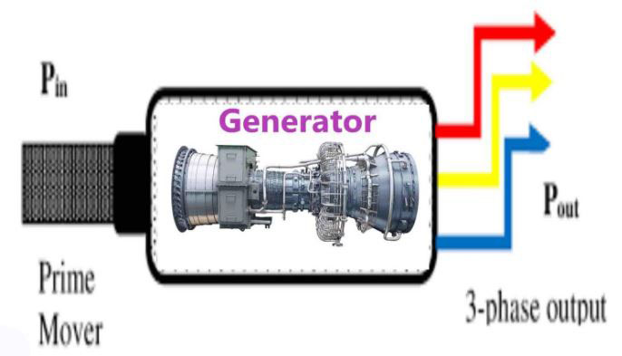
2. Why is black smoke produced in an engine?
Answer: Black smoke can be produced in an engine for various reasons, such as:
Operating under an overload or a very light load; wear and tear of piston rings or liners; low compressor pressure; incorrect fuel injection timing; improper tappet clearance; incorrect valve timing; or a faulty injector.
3. What is a carburetor?
Answer: The carburetor is the heart of a petrol engine. It essentially creates an air-fuel mixture in varying proportions, according to the engine's requirements.
4. What is latent heat?
Answer: Latent heat is the amount of heat absorbed or released by a substance of unit mass as it transitions from one state to another, without any change in its temperature.
5. Why does an engine produce white smoke?
Answer: White smoke can be produced in an engine for various reasons, including:
Water entering the combustion chamber, fuel contamination, excessively high engine temperature, or incorrect (advanced) fuel injection timing.
Question: Provide a brief introduction to piston rings.
Answer: Piston rings are widely used in various types of machinery—such as steam engines, diesel engines, gasoline engines, compressors, and hydraulic presses—and are extensively applied in automobiles, trains, ships, yachts, and other fields. A typical piston ring is installed within a groove on the piston; together with the piston, the cylinder liner, the cylinder head, and other components, it forms the combustion or working chamber.
Significance:
Piston rings are a key component of internal combustion engines; they create a seal between the piston and the cylinder wall, effectively containing the combustion gases. Automotive engines are categorized into two types: diesel and gasoline and because these fuels have different performance characteristics, the piston rings used in each type differ. Furthermore, not all piston rings are manufactured via the casting process.
With advancements in technology, the performance of steel high-strength piston rings is being enhanced to meet both operational engine requirements and environmental standards. This is achieved through various surface treatment processes—such as specialized heat treatments, precision finishing, chromium plating, gas nitriding, physical vapor deposition (PVD), surface coating, and zinc or manganese phosphating—which significantly improve the functionality of the piston rings.
Functions
Piston rings serve four primary functions: sealing, oil regulation (oil control), heat dissipation (heat transfer) and guiding (support). Sealing involves containing the gases—preventing combustion gases from leaking into the crankcase—thereby minimizing gas leakage and enhancing thermal efficiency. Gas leakage not only reduces engine power but also leads to oil-related issues. The primary function of the compression ring (gas ring) is to prevent such leakage. Meanwhile, the oil control ring is responsible for managing the oil film on the cylinder wall—ensuring that while excess lubricating oil is scraped away, a thin, uniform oil film remains to provide necessary lubrication for the cylinder, piston, and rings. In modern high-speed engines, particular attention is paid to the role of piston rings in regulating this oil film.
Heat conduction: The transfer of heat from the piston to the cylinder liner—in other words, the cooling effect. According to reliable data, heat from the piston crown is dissipated through the piston rings into the cylinder wall. Support: The piston also serves to minimize frictional resistance—ensuring smooth movement and prevents the piston from coming into direct contact with the cylinder wall. Piston rings are used to position the piston within the cylinder and prevent direct contact between the piston and the cylinder wall. Pistons in typical gasoline engines use two gas rings and one oil ring, while diesel engines also generally employ two gas rings and one oil ring.
Comparison between an alternator and a DC generator:
There are several differences between an alternator and a DC generator that merit special attention.
|
Alternator |
DC Generator |
|
1. It generates a variable voltage, which is supplied to the load via slip rings. |
1. Although a variable voltage is generated initially, it is subsequently converted into DC by means of a commutator and then supplied to the load. |
|
2. It contains a slip ring. |
2. It contains a commutator. |
|
3. Of the magnetic field and the armature, one must be rotating while the other remains stationary. |
3. The magnetic field will remain stationary, and the armature will rotate. |
|
4. The armature winding is open. |
4. The armature winding is closed. |
|
5. A DC supply must be provided to the field. |
5. No separate DC supply is required. |
|
6. The field core is made of laminated sheets. |
6. The field core is made of cast iron. |